
Active GNSS antenna design (Part I)
Once again, it’s been a long time. I should really devote more time to this blog… Well anyway, let’s get back to business! This time I’m posting about a little project I’ve been doing to support some activities at work. So, we’ve been working on some stuff with GNSS, but this time the receiver is designed to operate with an internal antenna as well as an external antenna, which can (should) be active and it is supplied through the coaxial cable. It is supplied through a dedicated LDO and has a bias tee network in place, so that it is perfectly isolated from the rest of the circuit to avoid noise from our circuit to sneak into the GNSS chain and screw the reception.
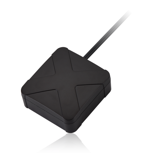
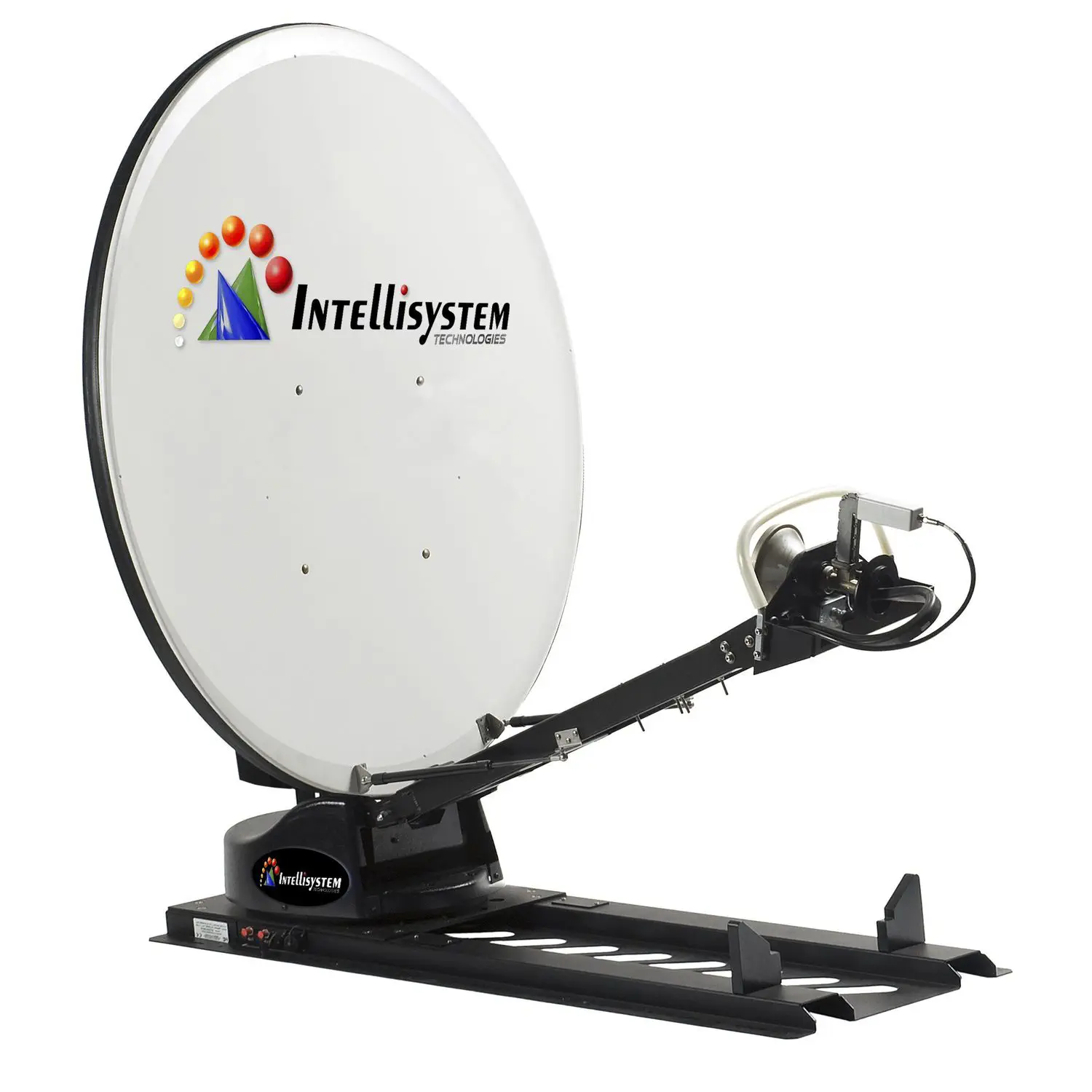
So, to test this device with an external antenna we need to acquire an external GNSS antenna and especially an active one. Of course, we did buy one, like this one here:
But I thought to myself, well I think I can make a similar, or even better, performance antenna for a similar price. Plus, that would be a nice little project I could do and would give a nice addition to my blog posts! And here we are…
When it comes to GNSS antennas there’s a myriad of solutions. Let me cover briefly some of these, knowing very well there’s more to each of the solutions and even sub-types within some of these options, but let’s keep it simple:
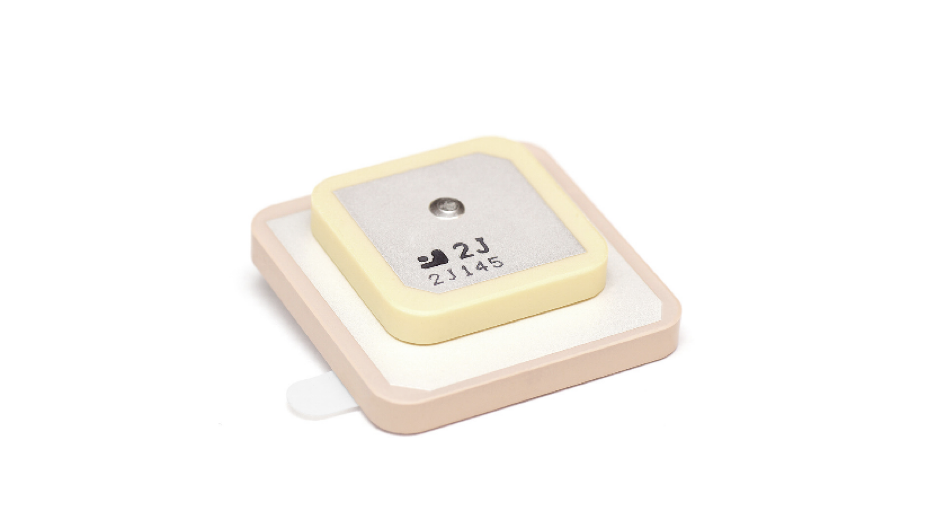
- Ceramic patch antenna - The ceramic patch antenna is the most common type of integrated antenna for small GNSS receiver systems. It’s compact size make it suitable for integration into portable devices. They have a reasonable gain and polarization purity, not exiling in either, they do a decent job. We’d need to make a PCB to integrate this antenna then add the amplifier and connector, no fun. Since we have a good volume availability, the ceramic patch antenna is not the best course of action. Designing one could be an option, but manufacturing can be expensive since the access to the ceramic substrates is limited.
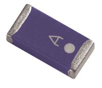
- Chip antenna - The chip antenna is also a common type of integrated antenna for GNSS receiver systems. As the ceramic patch, it’s main advantage is the very compact size, even smaller than the ceramic patch. But it comes at the cost of sacrificing gain as well as proper polarization. As well, designing a specific solution of this type could be very difficult (expensive) to manufacture. Here’s an example of a Yageo chip antenna taken from here:
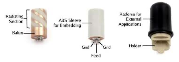
- Helical antenna - The helical antenna is many times found inside a monopole sleeve and make it look like a monopole antenna, but it is actually an helical antenna, which is usually linearly polarized. The gain is directly proportional to the length of the antenna which makes it hard to fit such a solution into our target volume (which is detailed further on). The balun is also tricky to design and can cut the bandwidth requirements short, besides it’s not easy to integrate the amplifier in this design.
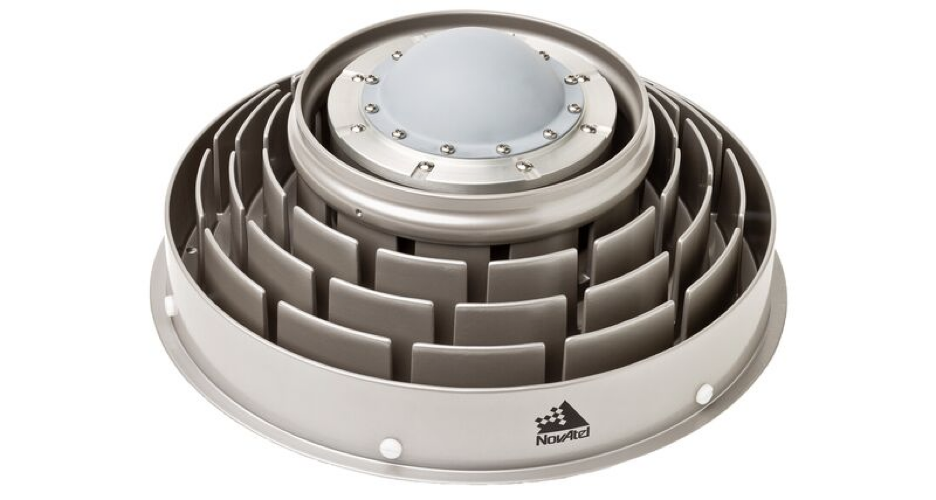
- Chocked ring antenna - These are typically the highest gain GNSS antennas. With directivity above 12 dBi, sometimes 15 dBi and integrated LNAs with gains in the order of 20-40 dB, these are GNSS antennas for sensitive applications and military applications. They provide very high accuracy. But, they’re usually big and heavy and are mostly targeted for fixed applications, more so given the aperture is usually small and requires some pointing during installation. Manufacturing such a solution, given its metal structure is also not cheap. Here’s an example taken from Novatel:
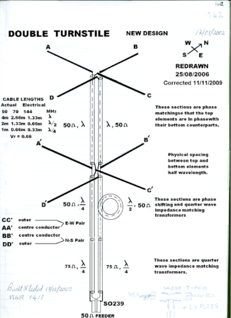
- Turnstile antenna - The turnstile antenna uses two orthogonal dipoles fed with 90º of phase in between each other in order to obtain the circular polarization, a second set of dipoles is fed with inversion of phase in order to direct the radiation pattern in the intended direction. Using the image principle, the second dipole set can be replaced by a ground plane. This is a possible solution, since this solution can be planarized in a PCB, the only downside is to achieve the correct gain with the limited height available.
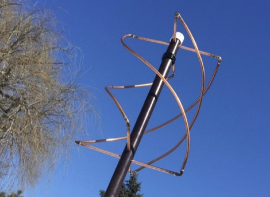
- Quadrifilar antenna - The quadrifilar antenna is a mix between the turnstile and the helical antenna, essentially the dipole elements of the turnstile are twisted along the propagation direction, like in the helical antenna. For us is not applicable for the same reason as the helical antenna. Save for the balun, which is non-existent in this case.
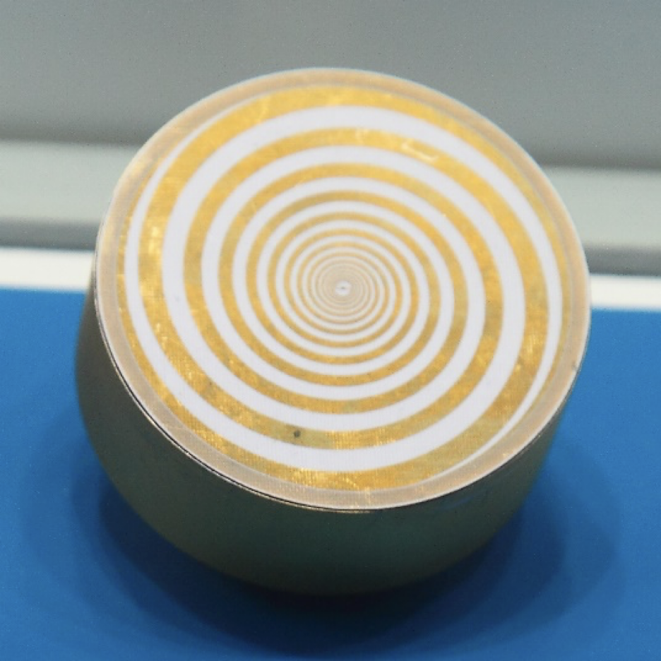
- Spiral antenna - The equiangular planar spiral falls in the category of “frequency-independent” antennas due to its very large bandwidth. The antenna is circularly polarized but its purity is dependent on the feeding arrangement. Since the basic element radiates equally in both hemispheres, a ground plane is usually needed to point the pattern in the right direction. The drawback is that spiral antennas do not provide high gain, this solution might still be viable, counting that we can achieve the required gain.
- Parabolic antenna - A widely known antenna type, but very bulky and nearly impossible to make fit inside the requirement volume package, and also, not a possible solution in terms of manufacturing. Here’s an example from a Spanish supplier.
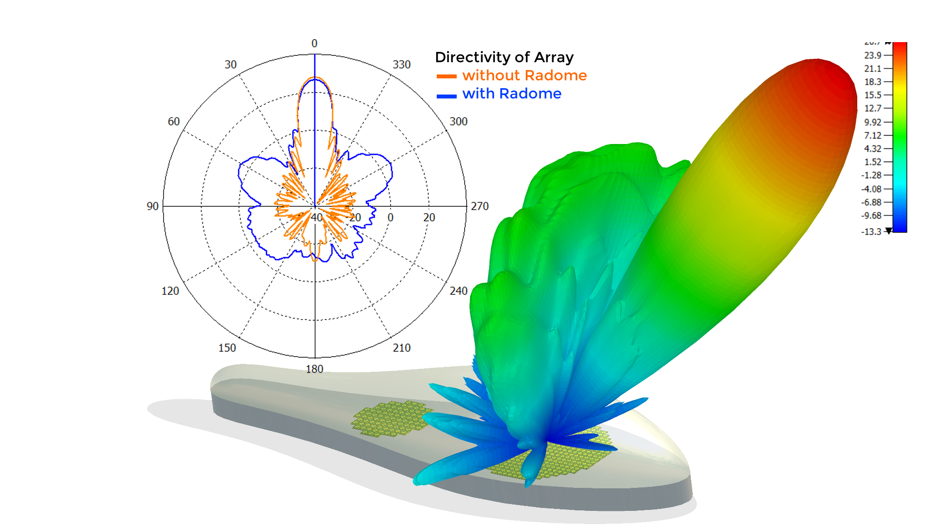
- Phased array antenna - This is the most advanced and complex option. It’s the solution that is capable to provide a performance comparable to the radome and the chocked ring antennas without the drawback of adjustments. But this is also a bulky solution and very complex with processing units and gain/phase adjusting elements. This is nearly impossible to fit inside the volume package required, and the cost and effort are tremendous, maybe some day I’ll venture into building such an antenna in a hobbyist approach, but not this time. Here’s an article advocating for the development of phased array solutions for satellite comm systems from Simulia (owner’s of CST software).
Having analyzed the typical antennas that can be used for GNSS antennas, the choice has fallen upon two candidates:
- Printed microstrip antenna with an air core, instead of ceramic.
- Printed turnstile antenna with a ground plane instead of mirror dipoles. And the second option was discarded because I’m not very good with artisanship, and a turnstile antenna is all about artisanship, so I’d end with a piece of metallic crap instead of an antenna, if I know me.
So, let’s define the requirements for this antenna:
- Frequency band: 1575 - 1610 MHz
- Maximum size: 100 x 100 x 20 mm
- Maximum weight: 300 g
- Passive gain: > 6 dBi
- Polarization: RHCP
- Active gain: > 20 dB
- Noise figure: < 1.5 dB
- VSWR: 2:1
Now, there’s also another rule for this challenge, the antenna must be designed and integrated into PCBs, so it is easier and cheaper to manufacture. Therefore, the use of ceramic patch antennas is not allowed. Also, the LNA (Low Noise Amplifier) must also be designed around a transistor, it doesn’t count to use a pre-packaged integrated LNA, otherwise where would be the fun?!

If I wanted to make it easier (and probably better), it would be preferable to opt for an integrated LNA like the BGA524N6 from Infineon. But instead, we’re going to design a LNA around a BFP640FESD, which is a HBT (Heterojunction Bipolar Transistor) tailored for low noise applications. The reason I chose this particular transistor is because I had it already in my component box without any destination and because it fits well this application.
To make this post shorter and to make it come out quicker, in this one I’ll focus only on the antenna design and results, on a next post I will focus on the LNA design and on the making of a housing for the antenna and integration of everything.
The antenna, well it’s an air-core microstrip patch antenna, similar to the one I’ve shown in previous posts for the RFID reader…

but with some minor twists!

I have to agree with officer Bortus here, it’s not very impressive, but that’s that. We want cheap, simple, functional and accurate without being a master artisan, there’s no way around it.
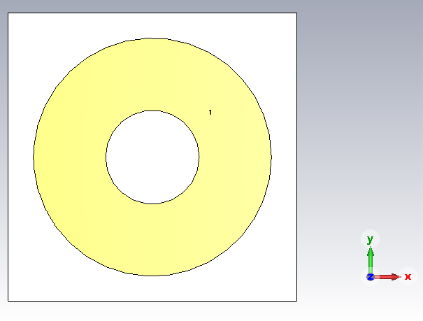
So the patch antenna itself is a ring antenna. Why a ring? Well, to use a square, I’d either have to rotate the coupler by 45º, or make some weird lines out of those ports (adding losses), because rotating the patch would make it impossible to fit within the 100x100 mm square PCB space. A circular shape gives me much more flexibility, but still the point is that I chose a ring instead of a filled circular shape. Remember my post about compensating the inductance of long feed points in air-core microstrip antennas? No? Shame on you, go check it out. Now, there’s another way to compensate for that added inductance from the feeding which is creating not a small, but a large slot in the middle of the patch. This works particularly well in circular patches, because the electric path through the middle of the antenna is increased smoothly. And that’s it.
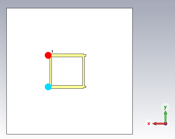
As in the case of the RFID antenna I’ve used a double feed with a hybrid coupler, but this time I dimensioned the lines to work at 1.575 GHz and were designed for a 0.8 mm (cheapest possible option after the 1.6 mm ones) thick FR-4 substrate. Here’s the pictures:
 |
 |
|---|---|
| Front view | Back view |
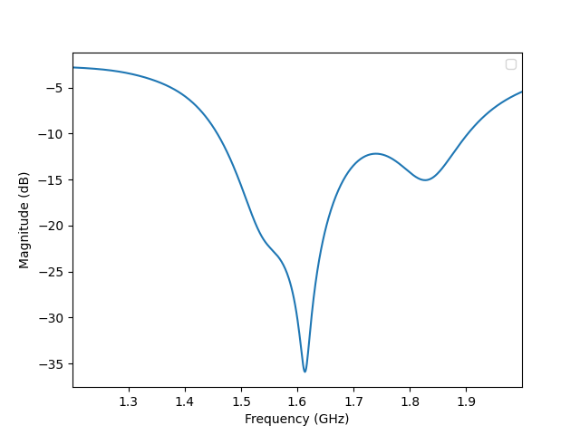
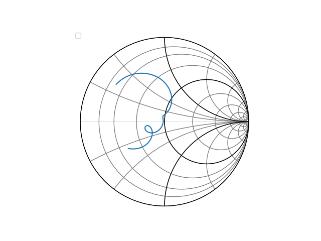
I’m not gonna bother you very much with the design process details, as I said above you can check my previous post about the air-core microstrip antenna, and you’ll get a good feeling on how to go about designing this one. To keep it short, here goes the simulation results for this antenna with the coupler included:
 |
 |
|---|---|
| S-parameters cartesian plot | S-parameters Smith chart |
And here’s the resulting radiation pattern:
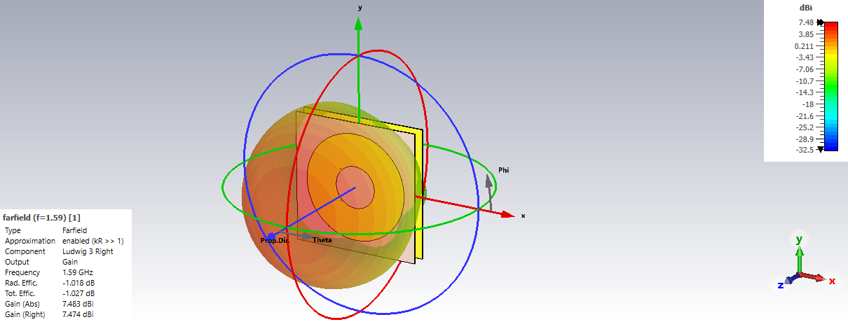
From the results we can we see we have a pretty decent bandwidth, covers all the L1 frequencies with margin. The antenna also shows a decent radiation gain and a very pure circular polarization, given the RHCP component have nearly the same gain in dBis as the total gain component (check the left bottom corner data on the [radiation] picture). That can also be shown in this plot of the gain and the axial-ration with frequency:
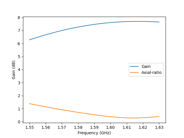
As you can see the gain is above 6 dBi around all band and the axial ratio is below 3 (actually even 2) dB around all band as well, between 1.55 to 1.63 GHz to be precise, which gives us plenty of margin for error!
At the time of this writing, I’ve already sent this design for manufacturing. As usual you can find these in my GitHub repository for antenna designs. Next post I’ll focus on the LNA section design and eventually I’ll show the assembly of everything and the measurements of the prototype.
So stay tuned folks!