
Active GNSS antenna design (Part III)
Alright, welcome to the third and last post about the GEN I Active GNSS antenna design saga. In this one I’ll post about the actual results obtained from the constructed antenna. And show you a monumental blunder I committed when designing both PCBs, but I’ll save stupid stuff for last. Next time I must remember to only start posts when I have the full project done and tested, but well, living and learning. But first, I’ll briefly explain something I forego in my previous two posts concerning the impedance match of the amplifier and was asked by a friend who happen to read this blog.
The input matching of the LNA designed in the previous posts is pretty miserable, and I really didn’t care to match it to 50 $\Omega$ and was solely concerned to match it to the lowest possible NF. Now, it’s common to have LNAs with input and output matching to 50 $\Omega$, and that is generally the best practice. This is very relevant since the LNAs can be integrated with band-pass filters at input and/or output, and these filters are usually designed for an input and output impedance of 50 $\Omega$, and when this is not the case, that can change the frequency response of the filter and completely alter its expected performance, hence ruining the receiver. In my particular case, there’s no filter, the antenna is directly driving the LNA, so the input matching is less critical. Now, of course, having a high input return loss will reflect the signal back to the antenna and may cause other sources of disturbance, cause de-polarization (remember I’m expecting RHCP and I have a hybrid square guiding those signals tightly), the reflected signal can cause destructive interference with incoming signals and the most obvious reduce the amount of power being delivered to the LNA for amplification. The former two impairments are very hard to predict, but the last one, it can be determined from the matching loss
\[ML_{dB}=10 \times log_{10}\left(\frac{1}{1-|S_{11}|^2}\right)\]remember the $|S_{11}|$ is in linear form.
In this case, from simulations, we’re looking at a return loss of -4 to -5 dB, which translates to 1.651 to 2.205 dB of matching loss. We can live with that given the 26 dB of theoretical gain we’re expecting from the amplifier.
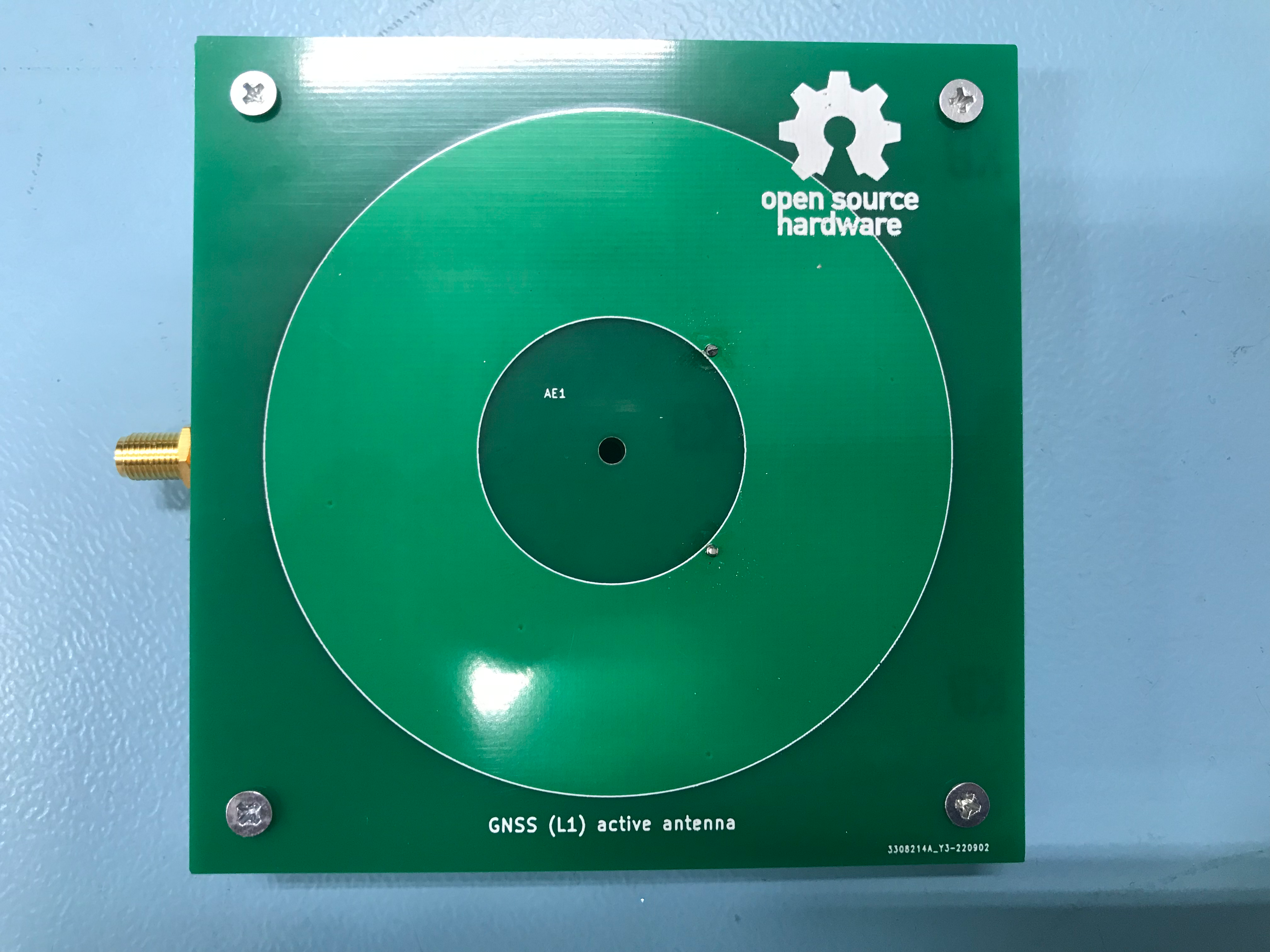
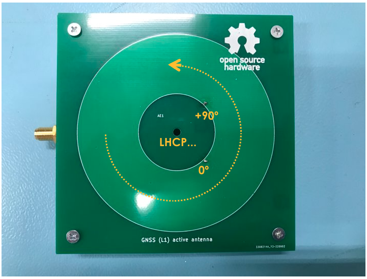
Before moving on to the measured results, here’s some nice pictures of the fabricated PCBs of the antenna and the LNA.
 |
 |
|---|---|
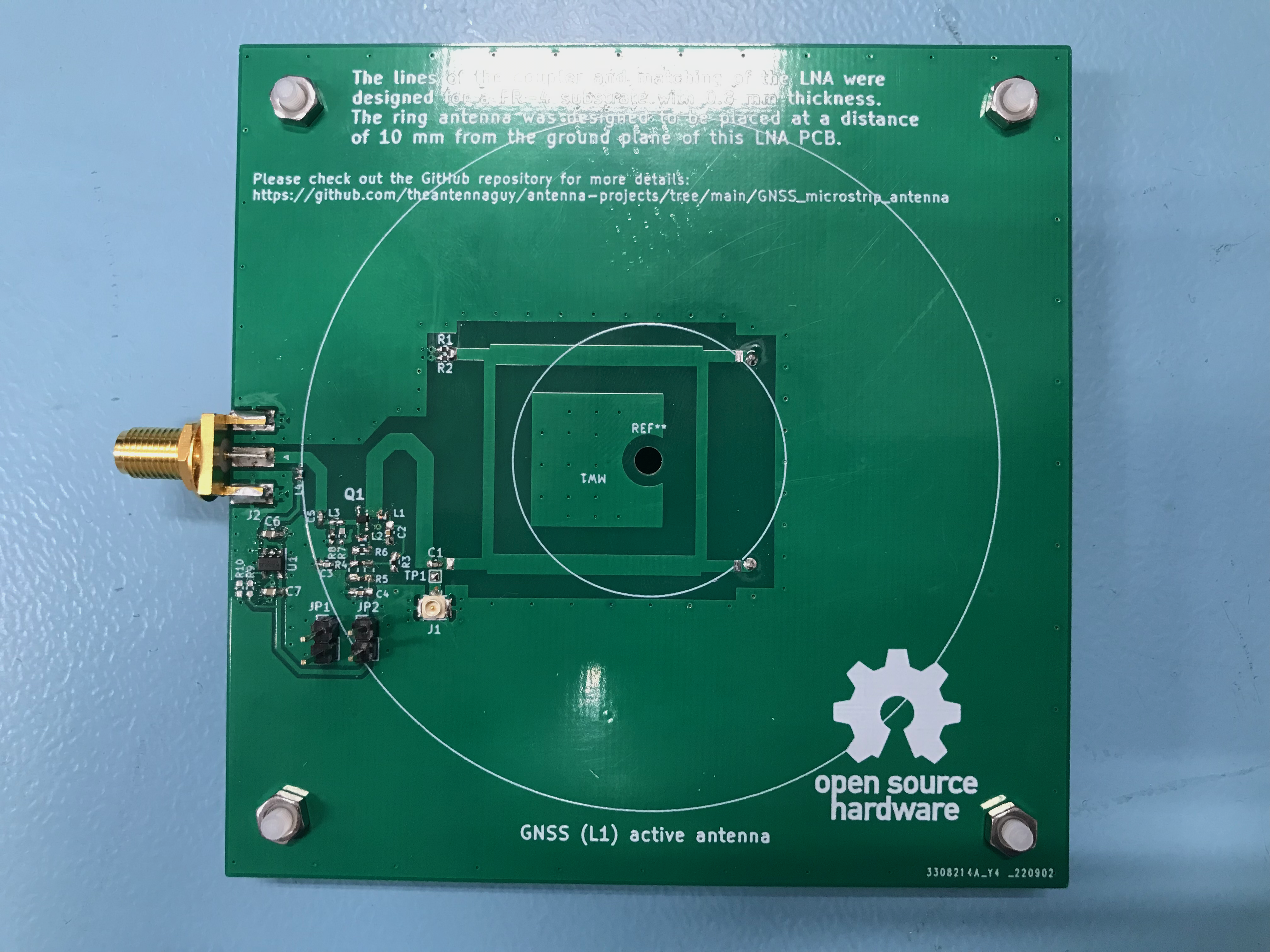
| Ring antenna PCB | LNA PCB |
And here’s the results from measurements of the antenna and the LNA. First lets look at the antenna S11, measured from that u.FL connector test port you see on the image on the right:
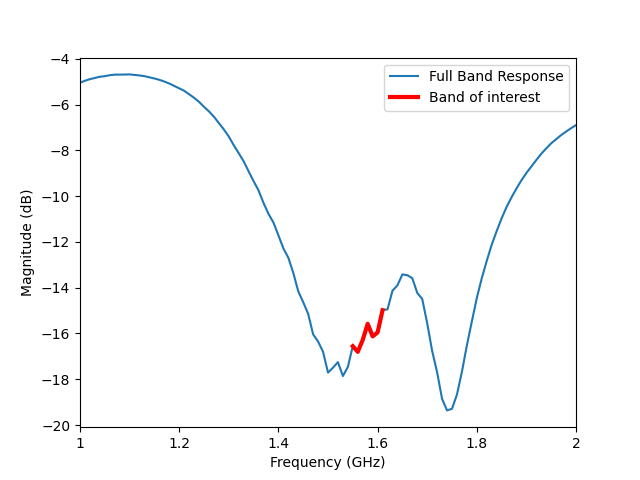
It’s not perfect, but with a coupler working at 1.575 GHz on FR-4 substrate in a low cost manufacturer (don’t get me wrong, these PCBs are amazing, but it’s not RF grade stuff), I’m pretty impressed. With a reflection coefficient below -15 dB in the entire band, it’s safe to say we’re good to move on.
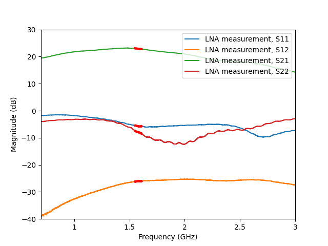
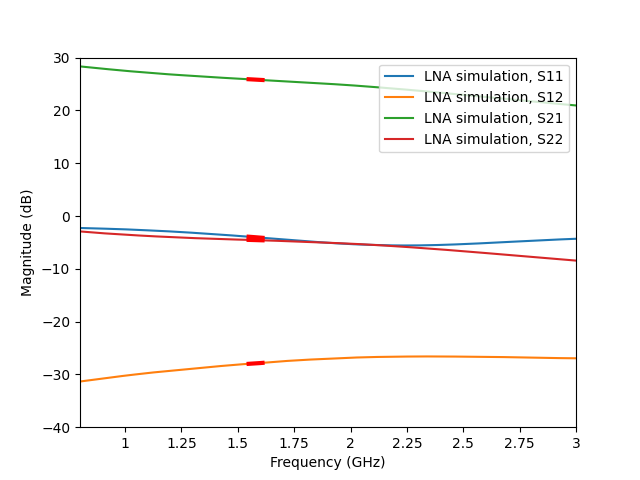
Now for the messed up part (but not only) of this project, the LNA, here’s the measured results of the BPF740F on this board:
 |
 |
|---|---|
| Measured S-parameters | Simulation S-parameters |
The results are not extraordinary, especially the gain, which is 3 dB lower when compared to the simulation results. Nevertheless, I’m pretty satisfied with the results all things considered. A diminished performance when compared to simulation was expected. Simulation project was tremendously optimistic when compared to the real thing, there were no 3D EM simulation of the board, even considering the real measured S-parameters for the output inductor, it was missing the line sections in between these output components. Plus the bias is not exactly correct to what was used as S-parameter file for the design. The board was tested using a bias-tee with 5 V bias, which resulted in 3.29 V out of the regulator, 2.56 V at collector and 16.5 mA IC bias, which is lower then the 22 mA planned which can also explain the lower gain.
Now I also compared this antenna with an antenna from a GNSS module evaluation kit, something like this:
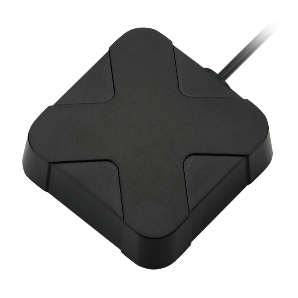
Unfortunately I could not find the specifications for the exact antenna from the module, but the pictured one is from Taoglas, you can find it here, and the specs are as follows:
| Parameter | Value |
|---|---|
| Peak gain | 2.9 dBi |
| Polarization | RHCP |
| Return Loss | <-7 dB |
| LNA Gain (@5V) | 30.1 dB |
| LNA Noise (@5V) | 2.5 dB |
| Dimensions | 53x50x17 mm |
Pretty good specs to be honest, especially the LNA gain, probably due to the dual stage LNA inside. Plus it also sports an input filter which helps a lot not saturating the LNA and causing other weird behaviors. The antenna I tested is not this exact one, but given it’s from Taoglas as well and with similar dimensions, I reckon should be pretty similar to this one.
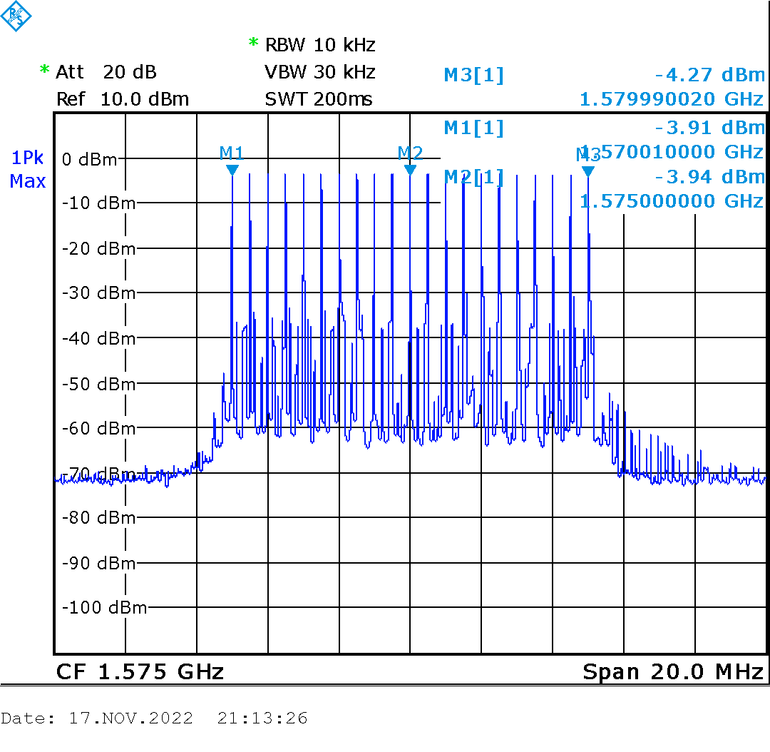
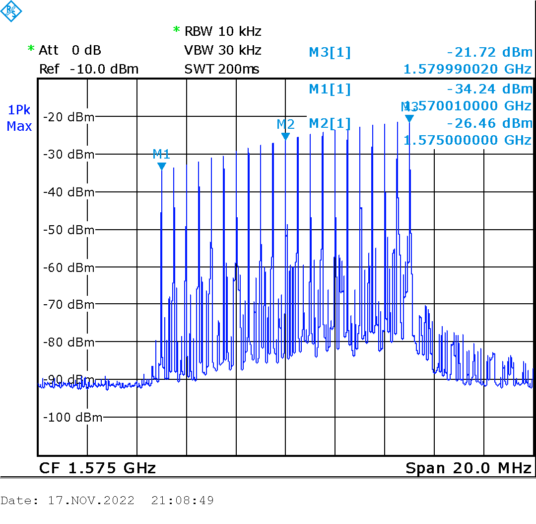
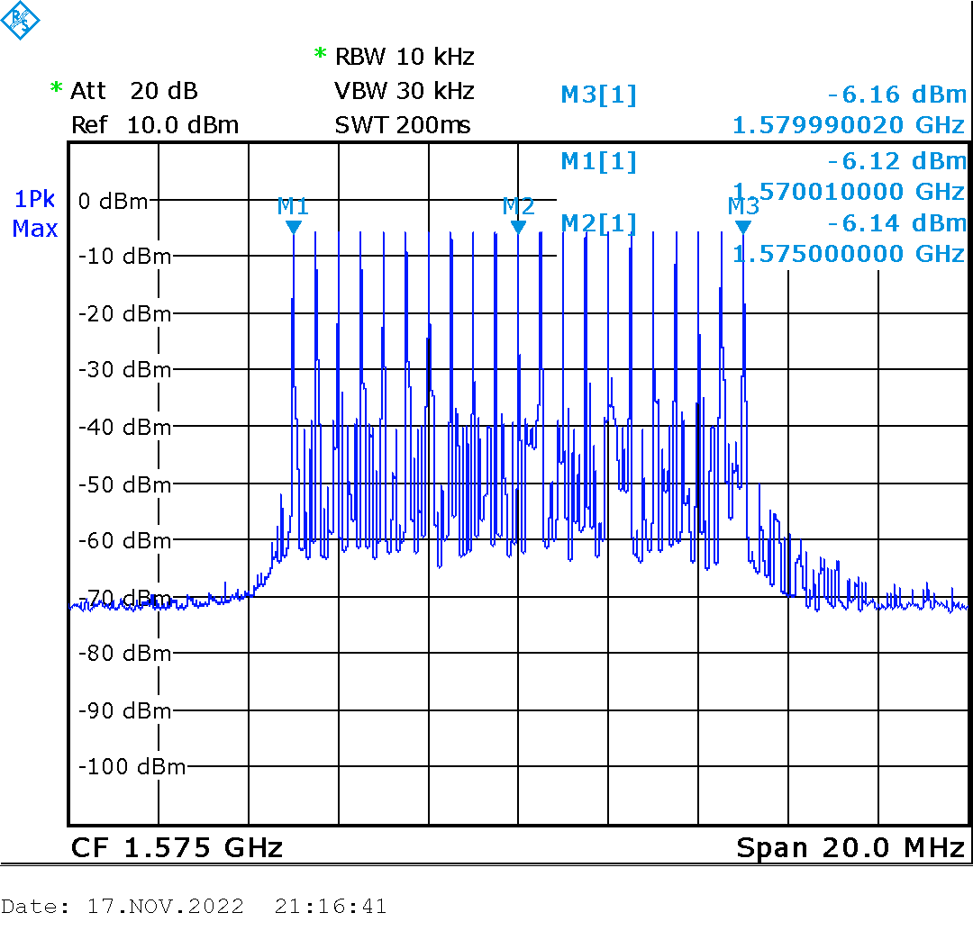
To make a comparison I connected a reference antenna with circular polarization connected to a signal generator and hooked the GNSS test antennas to a spectrum analyzer. I configured the signal generator to sweep frequencies between 1570 and 1580 MHz and recorded the received signals with both antennas:
 |
 |
|---|---|
| Measured transmission with EVM kit antenna | Measured transmission with my antenna |
Well that was extremely disappointing to see, and you better believe it got me scratching my head for some 15 minutes and double checking all the bias voltages around the LNA to make sure everything was nice, when I suddenly realized I was receiving more signal with the antenna upside down, that is, with the LNA board facing the transmitting antenna… and that’s when it hit me.
I messed up the hybrid coupler orientation on the board with respect to the patch!!!
I tested the antenna upside down against the EVM kit antenna and here’s a more just comparison:
|
 |
|---|---|
| Measured transmission with EVM kit antenna | Transmission with my (upside down) antenna |
Well, much closer in terms of performance, which is curious because the backside gain is pretty terrible, plus my LNA only has 23 dB of gain, still only 2.2 dB difference in received power. I wonder how much better it could really be if all things were properly done. On well, it’s a working GNSS antenna, not the antenna I needed but the antenna I deserve, I guess…
Finally I also tested both antennas with a M8N EVM kit from u-blox using the u-center application and both have shown pretty similar results in terms on numbers of satellites, $C/N_0$ (Carrier to Noise ratio) values as well as TFF (Time to First Fix).
Given all the mishaps that happened during the development of this GNSS antenna, it certainly deserves a GEN II with corrections. However, given it’s large dimensions, especially compared to the EVM kit antenna, I decided to work on a more compact version and also improve the amplification stage, that is, add a proper filter, maybe place two amplification stages, and I’m still deciding if I’ll design these or I’ll simply use a pre-packaged LNA.
Still, I’ll try to diversify, and my next post will be about something different than GNSS, but I’ll come back to GNSS in the future for sure.
So stay tuned folks!