UHF RFID Antennas - II - Microstrip patch antenna air core (Part I)
As I mentioned on my previous post, today’s post will be about the good old microstrip patch antenna.

There are two implementations for the microstrip patch antenna typically used for UHF RFID ‘Reader’ antennas, one with an air core and other with ceramic core. The advantage of the former is that it has a wider bandwidth (can usually accommodate the ETSI and FCC bands), better efficiency and therefore higher radiation gain and usually has a better polarization purity. The advantage of the later is that it is smaller. That’s it, on ceramic core microstrip antennas, you sacrifice all performance parameters for size. In some applications which are very restraining in terms of available space, it is essential to have the possibility to reach a compromise between the size of the antenna and its performance. Now, as I already mentioned, I’m not going to dwell on the theory of microstrip patch antennas, how they come to be and how they operate, I’ll explain a few things along the way, but my approach will be more on how you go about designing a microstrip patch antenna for this application. To know a little bit more about the workings behind the microstrip antenna, I’d recommend reading Randy Bankroft’s book.
So, first thing to do is to gather the requirements for the antenna. In this particular case, we’re aiming for an antenna that can cover the whole world bands, should have circular polarization, a minimum in-band gain of 4 dBc and maximum in-band axial ratio of 4. Summarizing:
| Frequency bandwidth (MHz) | 865.1 – 927.2 (center @ 896.2) |
|---|---|
| Minimum in-band Gain (dBc) | 4.0 |
| Maximum in-band axial ratio | <4.0 |
| Polarization | RHCP or LHCP |
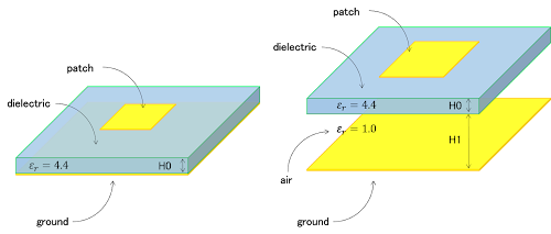
Besides the parameters, we need to know the available materials, in this case, we’ll want to use an inexpensive FR-4 type PCB and we’ll pick a 60 mil (1.524 mm) thickness board, and since we have no dimension limitation, let’s define an area of 250×250 mm for the antenna. It’s called an air core microstrip antenna, because the middle layer between the patch and the ground plane is, well, air. The reasons to use the air layer in the microstrip patch is essentially to solve two underperforming parameters of the regular patch with only the dielectric substrate in the middle: The bandwidth and the gain.

To calculate the patch dimensions, you can use the expressions on the previous book, or you can use an online calculator. The downside of using the air core, is that the patch size increases, since the permittivity of the substrate decreases. If you have H1 > H0, you can consider a permittivity of roughly 1.1 to calculate the patch dimensions and that should give a good starting point for further tuning.
Another important aspect is the driving technique for the antenna. There’s several ways to drive a microstrip patch antenna, for this particular case, we’ll use a coaxial probe feeding method. The coaxial probe feeding is achieved by driving a coax cable through the substrate, soldering the outside shield to the ground plane and soldering the coax pin directly to the patch, at a specific location where the impedance is close to 50 Ohm.
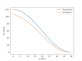
It is possible to calculate the approximate location where the 50 Ohm is located along the patch, in this case, I take and educated guess and then just tune it through simulation. To guess the correct position, we should consider that, as you move from the edge of the patch to the center, the impedance decreases, until you reach the center. At the center of the patch, the electric field strength is close to zero, essentially a short circuit, so the impedance is 0 Ohm. By knowing how the impedance varies when travelling along the patch, it’s easier to take a good guess (I’m not going to lie, experience also counts, that’s why they’re called “educated guesses”).
 |
 |
Below there’s a comparison of the reflection coefficient and the radiation gain between a square patch, built on a 120 mil (3.024 mm) thick FR-4 (er = 4.4) substrate, tuned for the RFID band, and a patch with an air core, with H1 = 20 mm.
 |
 |
The bandwidth of the air core patch is larger as well as the gain. From these results one can see the relationship between the permittivity and height of the substrate material and the antenna overall performance. With increased permittivity, there’s a shrinking of the patch size, but also a reduction in antenna bandwidth and gain. Plus, the height of the substrate also plays a vital role, since it counters the effect of the permittivity.
All is related to the fringing effect of the electric field at the edges of the microstrip patch, which is responsible for the antenna radiation. The more ‘loose’ the fringing effect is, the better the efficiency. The higher the permittivity and thinner the distance between patch and ground, the more ‘tight’ the fringing effect is.

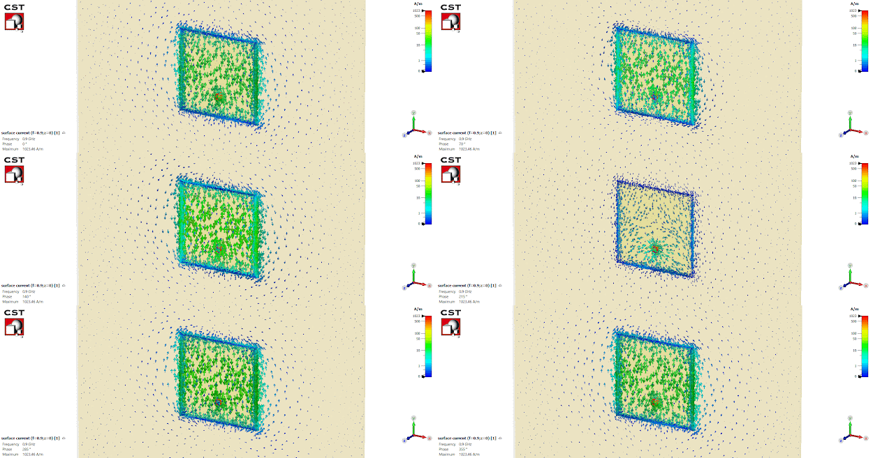
The reason to design a square patch, instead of the more natural rectangular patch, has to do with that fact that we’re designing a patch for circular polarization, and that’s easily attainable by starting from a square patch. Now you should know that decision comes at the cost of a reduction in bandwidth and efficiency of the antenna, but that’s a compromise we have to make to fulfill a mandatory requirement that’s the circular polarization. However, some things are still necessary, because a square patch has a linear polarization as one can see in the surface current distribution.

(As the phase progresses, the current points either upwards or downwards along the patch length.). So we need to make the polarization circular. However, there’s five different ways to get circular polarization with microstrip patches and this post is already getting long, so I’ll leave that to my next post.

