
UHF RFID Antennas - III - Microstrip patch antenna air core (Part II)
This is a continuation of my previous post on the air core microstrip patch antenna. It can be found here. At this point, we need to get the patch to radiate a circularly polarized wave (and correct the added inductance of the feed pin by the increased height).

Now, if looking at the microstrip patch through the cavity mode analysis, it’s possible to produce two fundamental frequencies of operation, set by the propagation mode that is activated in the patch, these are respectively TM10 and TM01. If the patch is fed along the length, we get the TM10, if it is fed along the width, we get the TM01…or is it the other way around? I always forget which is which! But it doesn’t matter, what is relevant is that we keep in mind that exciting fields in different places of the patch will excite different modes which might have or not the same resonance, but will have a phase delay between them. Feeding on one edge of the patch excites one mode, while feeding at the other edge excites the other mode. In a square patch, both modes have the same resonant frequency.
To achieve circular polarization, one has only to excite the patch in both modes simultaneously and with the correct 90º phase delay between them. Depending on which mode is delayed with respect to the other we can then achieve a circular wave that rotates to the left or to the right, achieving what’s referred as Left Hand Circular Polarization (LHCP) or Right Hand Circular Polarization (RHCP). There are five methods used to produce circular polarization on microstrip patch antennas:
- Feed the patch along the diagonal of the patch and adjust the width to the length ratio so that the TM10 and TM01 modes are produced with a 90º phase and realize CP - If the patch is square, feeding along the diagonal will generate a linear slant polarization, not circular.
- Using the same feeding orientation as before but using indentations and tabs to create the same 90º phase difference effect between modes.
- Feed at radiation center but cutting corners at the edges of the patch.
- Insert a slot in the middle of the patch. Either using a slant slot and feeding at radiation center or creating a horizontal slot and feeding at the diagonal of the patch.
- Using a dual feed technique – Feed at both radiation centers with 90º phase delay between the points to produce the 90º shift between modes.
Picture below shows the first four techniques mentioned before. If you want to learn more in depth about microstrip patch antennas, most of this stuff can be found in Randy Bankroft’s book.
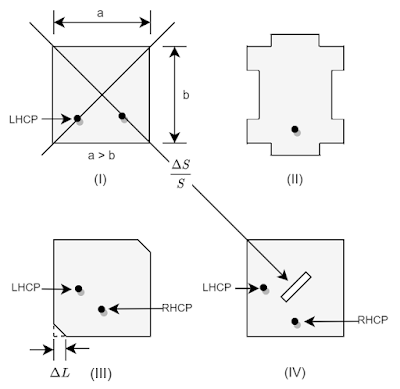
More or less all these techniques will produce a similar axial ratio bandwidth. However. techniques (II) and (IV) are difficult to implement in the air core antenna without interfering with higher order modes, hence messing it up completely. The easiest way to go about, for the air core microstrip patch, and most commonly used, is the technique III.

Technique (V) provides the larger axial-ratio band of all. However, it is the most costly solution and requires a specific feeding network, usually comprising a 90º-square hybrid in order to get two ports with the same amplitude and 90º phase delay in between them.
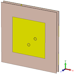
The cool thing about the circular polarization techniques is that they also increase the bandwidth of the antenna. Essentially because we’re exciting two modes with resonances that are slightly apart. If you look at the effect on the smith chart, you’ll see a knot in the curve. The frequency at the center of the knot is the frequency where the polarization is closest to be circular (because in reality polarization is actually an ellipsoid). If you look at the impedance response, on the real part, instead of one ‘mountain’ found at resonance, you’ll see two mountains for both resonances.
 |
 |
To demonstrate the stuff stated above, I built and simulated two microstrip patch antennas, using technique I and V. The .dxf of the designs are on github, they can be used to build a PCB layout, these are designed on regular 60 mil (1.6 mm) thick FR-4.
 |
 |
|---|---|
| Microstrip patch with corners cut | Microstrip patch with dual feed |
 |
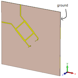 |
| Microstrip patch with corners cut (backplate) | Microstrip patch with dual feed (backplate) |
When you compare the S11 between both antennas, you can see the matched frequency bandwidth of the circularly polarized patches are much wider then the linearly polarized from last post, and that, as mentioned in this post, the dual feed method provides and even wider matched frequency band. So wide, I had to simulate the antenna between 0.7 and 1.2 GHz to find out the edges of the matched frequency band.
 |
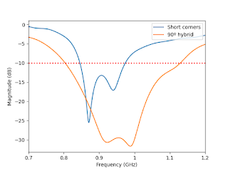 |
Besides impedance match, the circular polarization bandwidth is also much wider in the dual-feed technique. Coming at the cost of a degradation in the gain of the antenna.

Now, both of these antennas have RHCP (Right Hand Circular Polarization). This can be seen in the radiation gain results, but can also be easily observed in the surface current distribution, as shown below.
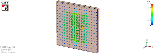
Unlike the current distribution on the microstrip patch from last post, in which the arrows either pointed upwards or downwards, in this case they rotate with varying phase. Now you’re probably thinking “Hey, you said they were RHCP but the arrows are rotating counter-clockwise!”

Now hold your horses Anakin before you get any respiratory problems and such. Actually, the convention about the polarization directions, is judged by the variation of the vector of the electric field when the wave travels away from the antenna! Check out this awesome video for more information on polarization.

Finally, to finish up, here’s a summary comparison of both implementations to the requirements we defined on last post.
| Parameter | Value | Corners cut microstrip | Dual feed microstrip |
|---|---|---|---|
| Frequency bandwidth (MHz) | 865.1 - 927.2 | ✅ | ✅ |
| Minimum in-band Gain (dBc) | 4.0 | ✅ | ✅ |
| Maximum in-band axial ratio | 4.0 | ❌ | ✅ |
| Polarization | RHCP | ✅ | ✅ |
So, according to this summary, to comply with all the requirements, the air-core microstrip patch with dual feed technique is the best choice. However, if we reduce the usable band to just the FCC band, then the single feed corners cut antenna is better. It can always be tuned to have the circular polarization at the ETSI band instead. But, in the current design, the dual feed antenna has another advantage, that it can produce LHCP or RHCP depending on the port of the hybrid square that is fed with the signal. So it is a compromise between cost/complexity and performance, as always.
If you paid close attention to the antenna pictures, you should be wondering what could be those circular rings on the patch. Remember that I said in the beginning of this post, we needed to compensate the increased inductance of the feed pin? Yeah, right, so this post is already long so… I’ll soon make a shorter post explaining about those circular rings that are found around the feed points in both antennas.
Stay tuned! (pun intended)