UHF RFID Antennas - IV - Microstrip patch antenna air core (Part III)
So, as I mentioned on my last post, here I’ll explain about those rings around the feed points on the microstrip antenna. Those rings are copper cutouts around the feed point of the antenna. Those cutouts, at high frequencies, are equivalent to a capacitor. That capacitor is used to compensate the series inductance that is introduced by the higher order modes being driven.

Also, the microstrip patch antennas are coaxially fed, the pin of the coax, at high frequencies, acts as an inductor, adding to the increased inductance effect, and the longer this pin wire is, the higher that inductance. That inductance is in series with the antenna and will impact directly on it’s input impedance.

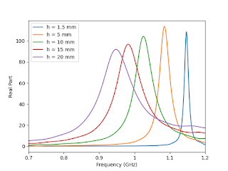
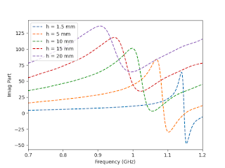
Here’s the variation of the input impedance of the microstrip patch with the variation in height (h) between the patch and the ground plane:
 |
 |
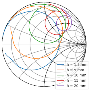
The plot on the left is the variation of the real part. Two things become clear from it: 1. We can confirm the relationship between the resonant frequency of the antenna with variation of height of the substrate; 2. The variation of impedance with frequency is smoother as the substrate height increases. That is why the microstrip patch antenna increases bandwidth with the height of the dielectric. The plot on the right is the variation of the reactive part, and besides the two points mentioned before, it’s also visible the increase in reactance with the increased height, which means the input impedance is more inductive as the height increases. This effect can also be seen by looking at the Smith chart. In the Smith chart, what happens is that the impedances are more and more concentrated on the top side of the Smith chart, referred as the inductive side of the Smith chart. Conversely, the lower half of the Smith chart is the capacitive side of the Smith chart.

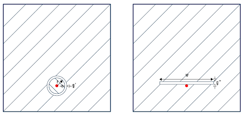
And now you’re asking “That’s all well and fine, but then how do you fix that impedance?”. Well, you have to compensate an inductance, you use it’s nemesis, the capacitor! If you place a capacitor in series with the input, you can compensate that effect. Easy solution, and if the antenna was fed by a PCB trace that would be super easy. But, soldering a capacitor on a coaxial pin can be quite cumbersome, and costly if you start thinking about mass production of the assembly. Therefore, a more creative way, was to modify the patch structure in order to impose a series capacitance at the feeding point. This can be achieved with two structures:

The one on the left is an annular ring cutout, as I used on the microstrip patch antennas from my previous post, the other is a rectangular cutout right next to the feed point. The expressions to calculate the dimensions of these structures can be found in RF books under the printed capacitors section, but in this particular structure they fail on the prediction, therefore, the best to way to find the right dimensions is through simulation. Can be quite daunting the first time, but the trick is to keep looking at the movement on the Smith chart as the parameters of the slot are varied. They also slightly change the excited modes, so the resonance shifts. Hence, in modern EM simulation tools and a reasonable computer, the best approach is to first find approximate values through sweeping of the parameters and then optimize with the patch length, the feed point location and the slot parameters. If you start with the optimization right away, good luck…

And that’s it folks. Told you this was gonna be a short one! For my next trick, I’ll fulfill my promise of the first post and start talking about the tag antennas, later I’ll come back to some more exotic reader antennas.
Stay tuned (use a capacitor if necessary).
