UHF RFID Antennas - I - The basics
This is the first official entry to the blog!

So the other day I was watching this video and I thought “Hey I can actually do that!” (Design UHF RFID antenna tags). So I decided the first entries to this blog would be dedicated to UHF RFID antennas (I don’t even feel qualified to qualify that idea…).
I always found RFID technology very interesting. It’s a shame that it is really obscured, especially the UHF. One can find some applications here and there, and many times don’t even realize it’s RFID. Still, I always get the feeling that it is a highly underrated technology, I mean, it has the potential to offer so much, but somehow, it’s not so ubiquitous as it should have been. Think about it, it’s a wireless communication system, where the mobile parts actually work without the need for batteries, but they can send data back to a transmitter without any local power source available to them. That’s as close as we can get to ‘wingardium leviosa’ in our world (Well, there’s many interesting techs out there that are rather magical, but this one is cool).

Now I should focus on the antennas, but I thought I’d give a little explanation behind the workings of RFID. I’m not going to be exhaustive, if your interested in knowing more, I can recommend reading Finkenzeller’s book on RFID.
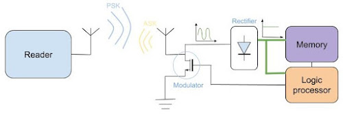
On the video I mentioned in the beginning, they provide a quick explanation to how an RFID system works, check minute 22:30. I’d only like to add a little detail that I thought missing. Actually the description of Scotty is accurate, in the sense that the tag really converts the RF signal to a usable DC voltage in order to power up in the internal logic circuit to read the query info, read its corresponding ID from memory and bias an actuator (transistor), but then, it does not generate a signal to transmit back, as explained in the video, the ‘Tag’ actually reflects the signal back to reader. This happens as follows, the ‘Reader’, after sending a ‘Query’ to the air, keeps an unmodulated carrier wave on the air, in the same frequency, for a short time, this is the time needed for the ‘Tag’ to respond. When this carrier wave reaches the ‘Tag’, it will tune/de-tune it’s input impedance of the antenna, therefore, absorbing or fully reflecting the incoming carrier wave, actually creating what is called an ASK (Amplitude Shift Keying) modulation that the reader can then decode.
Of course this methodology does not allow communications with high data rates, actually it is very constrained and only useful to send a few bytes. Even though there have been people in the academia developing complex modulation schemes that could be employed in passive RFID tags and boost the available data rates. Now, I won’t dig to deep into this subject because there’s a lot to explore and a lot that I don’t know about it. As is the premise of this blog, I’ll focus essentially on the antennas.
There’s several antennas on both sides of the system, especially if you starts looking at proposals in scientific publications from IEEE, but commercially there’s in essence three types of base antennas for the ‘Reader’ and two types for the ‘Tag’ antennas.
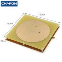
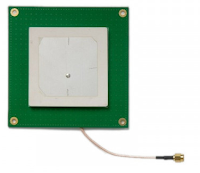
On the ‘Reader’ side, the antenna choice is usually a compromise between the size and weight to the gain and bandwidth. Higher gain antennas allow longer reading ranges for the RFID system, but gain of antennas is intimately connected to their size, and many applications sacrifice reading distance to have a more compact solution. The three typical antennas found on commercial RFID products are the good old microstrip patch antenna, either with an air core or with ceramic core and the quadrifilar spiral antenna. Here’s some examples:
 |
 |
 |
|---|---|---|
| Microstrip patch air core | Microstrip patch ceramic core | Quadrifilar spiral antenna |
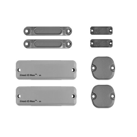
On the ‘Tag’ side there’s less variety. Even though there’s a lot of different and weird designs for these antennas, most of them are based on the same antenna principle, only changing the shapes to conform to different sizes, make them more square or more rectangular, or round, etc. Most tag antennas are based around dipoles with a T-matching network, however, there’s a few variations to this rule, one is the 4-arm crossed dipole antenna found in some commercial ‘Tags’ as well other more exotic antenna implementations for ‘Tags’ that work under special conditions, like attached to metallic objects. Here’s some examples:
 |
 |
 |
|---|---|---|
| Dipole | Double-dipole | RFID tag for Metal objects |
Besides the examples shown above, there’s a lot of variants for all sorts of applications, but the antenna types usually revolve around dipoles or the more specific constructions for tags that are to be attached to metallic surfaces.
Well, I don’t feel like going further than this today. On the next posts I’ll focus on exploring in more detail the construction of some of the antennas shown here. With the first being about the good old microstrip patch, starting with the air core, then I’ll move to the ceramic core. Eventually I’ll reach the tag designs as promised in the beginning of this post.